

Connecting Lines :
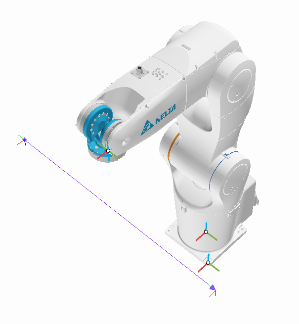
When the checkbox is selected, the taught coordinate points will be connected in sequence with straight lines, showing a start and end point. The connecting line between the start and end points will have an arrow indicating the direction.
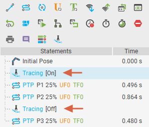
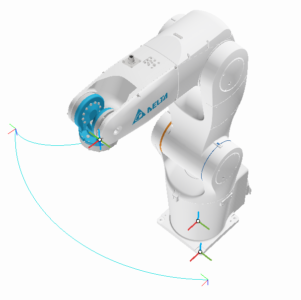
The tracing statement in the program editor will track all points between the start and end of the statement, drawing the actual movement path as lines. This helps users observe whether the movement path interferes with other mechanisms. To use this feature, in addition to selecting the checkbox, you need to add tracing statements before and after the points where you want to display the trajectory in the program editor and set them to active. The trajectory will then be displayed in the 3D world during simulation.
Click the gear icon to display the tracing settings page
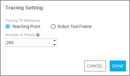
Tracing TF Reference:
Teaching Point: Tracks and draws the trajectory based on the coordinate points recorded in the program editor.
Robot Tool Frame: Tracks and draws the trajectory based on the default tool coordinate points of the arm.
Number of Points: This setting defines the maximum number of points. The trajectory in tracing is generated by connecting points with straight lines at each time step (frames per second). If the number of points remains constant, a lower time step value results in a shorter trajectory, while a higher time step value results in a longer trajectory. Increasing this value will produce longer trajectories on the screen, but more points will have a greater impact on performance.